Lab 3: Multicast for Improved Data Reuse in Multi Core Matrix Multiplication
Introduction
In Lab 2, you implemented multi core matrix multiplication with data reuse within each core. Each core read tiles of input matrices from DRAM into its own circular buffers (CBs) and reused them locally across multiple multiply-accumulate steps. However, data was not reused across cores: each core read its own tiles from DRAM, even when neighboring cores needed the same data.
Ideally, each piece of data should be fetched from DRAM only once and then reused by all cores that need it. On Tenstorrent devices, cores do not have direct access to each other’s circular buffers (CBs), but they are connected by a 2D Network on Chip (NoC) that allows them to pass data to each other. While sending data over the NoC is more efficient than reading data from DRAM multiple times, it still introduces overhead that we would like to minimize. The NoC supports unicast and multicast operations. Unicast allows a sender core to write data to a single destination core. Multicast allows a sender core to write the same data to multiple destination cores in a single NoC operation, minimizing the overhead when the same data needs to be sent to multiple cores.
In this lab, you will:
Learn how to use simple multicast to send tiles from one sender core to multiple receiver cores.
Understand how semaphores, device coordinates, and multicast addressing work together.
Apply multicast to your Lab 2 multi core matrix multiplication so that tiles of
AandBare reused across cores, not just within a single core.
High-Level Motivation
Consider the example matrix multiplication shown in Figure 1.
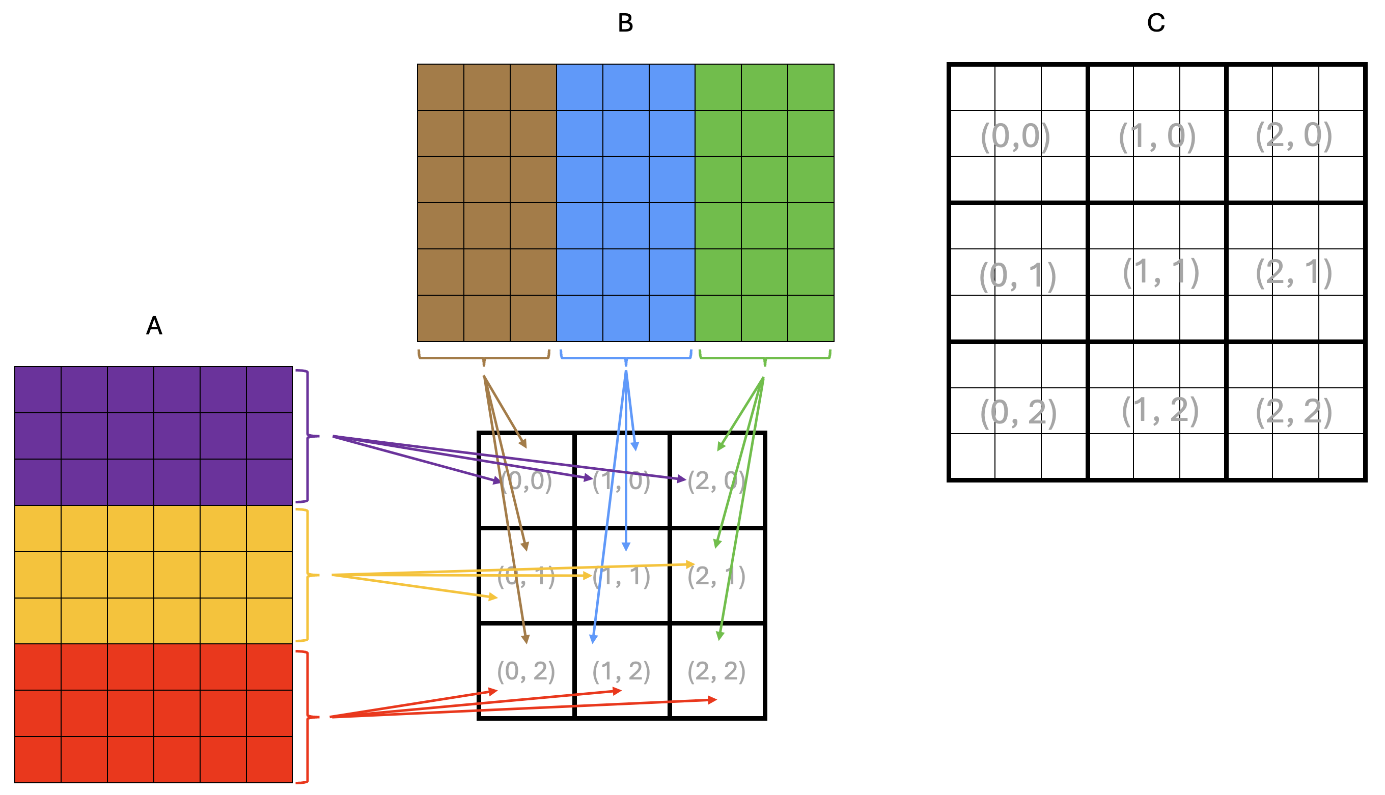
Figure 1: Example matrix multiplication on a 3x3 core grid
Each square in Figure 1 represents a tile, and the dimensions of the matrices are 9x6 tiles
for A and 6x9 tiles for B, resulting in a 9x9 tile output matrix C.
The squares in the middle of the figure represent the core grid, with each square labeled
with its core coordinates (x, y). The core coordinates are also shown over the output
matrix C to indicate the core that computes the corresponding rectangular block of tiles.
From the basic matrix multiplication algorithm, we know that computing an element of the output matrix C
requires all elements of the corresponding row of A and the corresponding column of B.
The same applies when computing tiles or rectangular blocks of tiles of C.
This means that all cores in the same row need the same tile rows of A,
and all cores in the same column need the same tile columns of B.
Arrows in Figure 1 show tiles being read from DRAM into the cores’ on-chip SRAM:
all cores in the same row read the same tile rows of A, and all cores in the same
column read the same tile columns of B.
Since DRAM bandwidth is limited, this is inefficient because the same data is read multiple times from DRAM. Instead, we would like to load a tile from DRAM once and share it across all cores that need it through the NoC. A possible way to achieve this is shown in Figure 2.
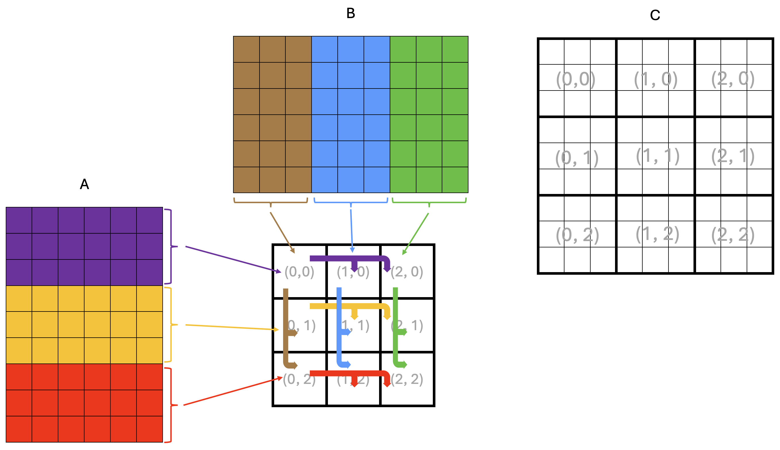
Figure 2: Example matrix multiplication on a 3x3 core grid with multicast
In the example in Figure 2, only the leftmost core in each grid row reads tiles of A from DRAM,
depicted by thin arrows in the figure.
Each leftmost core stores the tiles of A into its own CBs for its own computation, just as it did in Lab 2.
However, it now also multicasts the tiles of A it read from DRAM to all the other cores in the same row.
Similarly, only the topmost core in each grid column reads tiles of B from DRAM, storing them into
its own CBs for its own computation, and multicasts these tiles to all the other cores in the same column.
The multicast operations are depicted by thick arrows in the figure.
In the rest of this lab, you will first work through a simple example program demonstrating NoC and multicast features, and then retrofit your Lab 2 matrix multiplication with data reuse solution to use multicast.
Background: Tenstorrent NoC and Multicast
The Network on Chip (NoC) is a high-bandwidth 2D torus interconnect (often visualized as a 2D grid) that connects:
All Tensix cores
DRAM controllers
PCIe interfaces
Ethernet cores (for multi-device systems)
The NoC transfers data between components of the device, including between DRAM and on-chip SRAM. As you have seen in earlier labs, a TT-Metalium programmer does not need to understand all of the hardware details to use the NoC. In this lab, we will expand our use of the NoC to include multicast operations to transfer data between cores. For more detailed information about the NoC, refer to the resources listed in the Additional Information section at the end of this lab.
In TT-Metalium, NoC multicast is a data movement operation where one core writes directly into the on-chip SRAM of multiple other cores with a single command. The sender core specifies a group of destination cores and a destination memory address, and the NoC hardware delivers the data to that address on every destination core. Unlike a “pull” model where receivers issue read requests, multicast is a “push” model: the sender pushes the data into the receivers’ on-chip memories.
From the receiving core’s point of view, a multicast operation writes tiles straight into its on-chip SRAM, typically into a location it has already set aside in a circular buffer (CB). The receiver does not need to perform any explicit read or copy for the data itself; it only needs to prepare space and indicate that it is ready to accept a tile (for example, by reserving a CB slot). Once the multicast completes, the tile is simply present in the CB, ready to be consumed by the compute or writer kernels just like any other locally produced data.
We will illustrate the multicast operation with a simple example program in the next section.
Example Multicast Program
The main host program for the multicast example is ttnn/examples/lab_multicast/lab_multicast.cpp.
The program creates a 2D tensor and fills it with random data.
One sender core uses a reader kernel to read tiles of this tensor from DRAM and also multicasts them to three receiver cores.
The flow of data is shown in Figure 3.
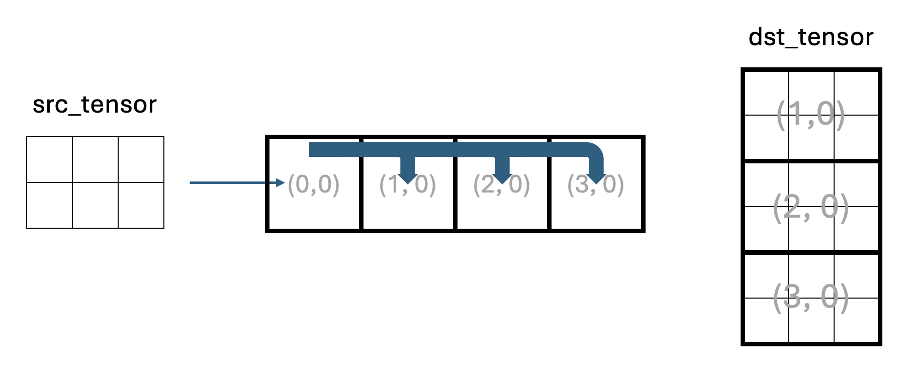
Figure 3: Data flow in the multicast example program
Core (0,0) is the sender core and cores (1,0), (2,0), and (3,0) are receiver cores.
Receiver cores do not read the input tensor from DRAM, but receive tiles via multicast from the sender.
Each receiver core has three kernels:
A reader kernel that manages the CB and signals to the sender core when it is ready for the next tile.
A compute kernel, which simply copies each tile to the output CB. In a real application, this is where computation would happen.
A writer kernel that writes each tile into an appropriate region of the output tensor in DRAM.
The host reads back all receiver outputs and verifies that the output tensor contains three copies of the original tensor stacked vertically. Note that the number of tiles in Figure 3 is symbolic and does not accurately represent the number of tiles in the actual program.
Synchronization with Semaphores
Given that multicast uses a “push” model in which the sender writes data directly into the receivers’ on-chip SRAM, it is important to coordinate execution between the sender and receivers to avoid data corruption and race conditions. This coordination is done using semaphores. In general, a semaphore is a small shared variable used to coordinate concurrently running code. For example, one semaphore can signal that receivers are ready for data (for example, after reserving a CB slot for an incoming tile), and another can signal that data has been sent (i.e., written to receivers’ memory).
In TT-Metalium, a semaphore is an integer value stored in on-chip SRAM that multiple cores can read and update. Typical use cases for semaphores include:
A core increments or sets a semaphore to signal that some condition is now true (for example, “a receiver is ready” or “a tile has been sent”).
A core waits until the semaphore reaches a target value before proceeding, ensuring it does not read data or start an action too early (e.g., before the data has been written to memory).
A semaphore can be created on one or more Tensix cores using the CreateSemaphore host-side API,
which allocates and initializes a semaphore in on-chip SRAM and returns a semaphore ID.
For example, in lab_multicast.cpp, there are two semaphores created:
uint32_t receivers_ready_semaphore = CreateSemaphore(prog_state.program, all_cores_logical, 0);
uint32_t tile_sent_semaphore = CreateSemaphore(prog_state.program, all_cores_logical, INVALID);
where prog_state.program is the TT-Metalium Program that these semaphores belong to,
and all_cores_logical is the logical core range on which to create the semaphore
(in this example, all four cores). Finally, the last argument is the initial value of the
semaphore on each core. In this example, 0 is used for the receivers_ready_semaphore
to indicate that none of the receivers are ready to receive a tile.
Similarly, tile_sent_semaphore is initialized to the INVALID value because initially the sender
core has not sent any tiles. INVALID and VALID are constant integer values defined in the
TT-Metalium API to make the code more readable.
The IDs returned by CreateSemaphore are then passed as kernel arguments so that kernels can use
them to access the semaphore on the core they are running on.
High-Level Multicast Protocol
Before looking at the code, it is helpful to describe the multicast protocol at a high level, as shown in Figure 4.
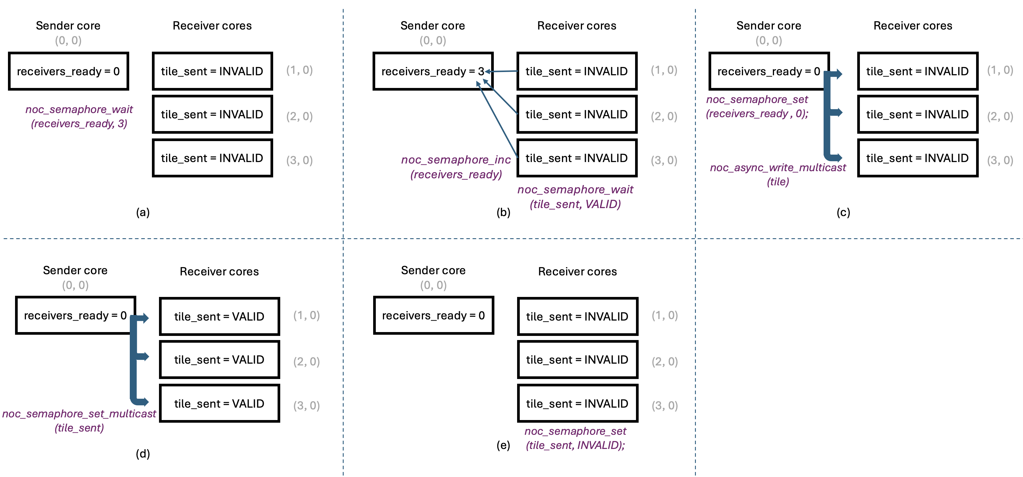
Figure 4: Multicast Protocol
Figure 4(a) shows the multicast protocol near the beginning of kernel code execution,
with all semaphores at their initial values.
The sender core has just read a tile from DRAM into its input CB, and is ready to multicast it
to other cores. However, it must wait until all receivers signal that they are ready for the tile.
The sender does this by waiting for the receivers_ready semaphore, which resides
in the sender’s on-chip SRAM, to reach the number of receivers (three in our example program).
Waiting on a semaphore is a blocking call and does not involve any NoC traffic since the
semaphore is in the local on-chip SRAM.
Receivers, for their part, must allocate space in their input CBs for the incoming tile and then
signal that they are ready to receive the next tile. They do so by calling noc_semaphore_inc
on the receivers_ready semaphore in the sender’s on-chip SRAM, to increment it by 1.
This is shown in Figure 4(b).
Note that this increment does require a NoC transaction, since the receivers_ready
semaphore is in the sender’s on-chip SRAM. These transactions are unicast transactions:
each receiver core sends an independent increment transaction to the sender core, so the order
of increments is not guaranteed. However, incrementing a semaphore is an atomic operation, so
the sender will eventually see the correct number of receivers ready for the tile.
The sender core does not send the tile until all receivers have indicated they are ready.
After indicating readiness, each receiver core waits for the sender to multicast the tile to it.
This is done by waiting on the tile_sent semaphore in the receiver’s on-chip SRAM.
This wait operation also does not involve any NoC traffic since the semaphore is in the local on-chip SRAM.
Once the sender core has seen the correct number of receivers ready for the tile,
it can multicast the tile to all receiver cores in one operation, using the noc_async_write_multicast
function. This is illustrated in Figure 4(c).
The sender core also resets the receivers_ready semaphore to 0 to avoid accidental reuse of
the same semaphore value, and in preparation for the next tile.
Since the receivers_ready semaphore is in the sender’s on-chip SRAM, this does not require any NoC traffic.
Having sent the tile to all receiver cores, the sender core must signal to the receivers that the tile has been sent.
This is done by calling noc_semaphore_set_multicast on the tile_sent semaphore in the receiver’s on-chip SRAM,
to set it to VALID. This is illustrated in Figure 4(d).
Since we wish to update the tile_sent semaphore on all receiver cores, this requires a NoC multicast transaction.
Finally, once a receiver core observes that its tile_sent semaphore has been set to VALID,
it can proceed to consume the tile. Once the tile has been consumed, the receiver core calls noc_semaphore_set
on the tile_sent semaphore in its own on-chip SRAM, to set it to INVALID to prepare for the next tile.
Similar to the earlier noc_semaphore_set call, this does not require any NoC traffic since the
semaphore is in the local on-chip SRAM. This is illustrated in Figure 4(e).
As can be seen, the state of all the semaphores is now the same as at the beginning of the protocol,
ready for the next tile to be multicast.
This high-level protocol helps explain the overall flow of the multicast operation. The following sections describe TT-Metalium APIs used to implement it.
Overview of Provided Files
The example multicast program located in ttnn/examples/lab_multicast/ contains the following files:
-
Host program:
lab_multicast.cpp- Creates kernels, CBs, and semaphores on appropriate cores and launches kernel execution.
-
Dataflow kernels:
kernels/dataflow/mcast_sender.cpp- Reads tiles from DRAM and multicasts them to receiver cores. This kernel runs only on the sender core.kernels/dataflow/mcast_receiver.cpp- Receives tiles via multicast into its input CB. This kernel runs only on the receiver cores.kernels/dataflow/write_tiles.cpp- Writes tiles to DRAM at this receiver’s region of the output tensor. This kernel runs only on the receiver cores.
-
Compute kernel:
kernels/compute/tiles_copy.cpp- Copies tiles from input CB to output CB. This kernel runs only on the receiver cores.
Logical vs. Device Coordinates
The example multicast program uses device coordinates, a new concept not previously seen in Labs 1 and 2. So far, we have been using logical coordinates to describe how you want to assign work to cores in a program. Logical coordinates assume that the physical layout of Tensix cores is a contiguous grid of compute cores. However, a typical Tensix device also contains multiple DRAM controllers, multiple Ethernet cores and a PCIe interface. Since the NoC interconnects all these components, it needs a coordinate system that includes all components, not just compute cores.
The Tenstorrent architecture defines more than two coordinate systems, but for the purposes of TT-Metalium programming for this lab, we only need to consider logical and device coordinates. Note that device coordinates are also referred to as virtual coordinates in the Tenstorrent architecture documentation.
The host code always uses logical coordinates (e.g., when creating kernels and CBs), and the compiler takes care of converting
them to device coordinates when needed, making the program easier to write and understand.
However, to maximize performance, we want to avoid performing such coordinate conversions in device kernels.
Therefore, device kernels must use device coordinates when performing NoC operations.
To facilitate this, TT-Metalium provides the worker_core_from_logical_core function that is called on the host to
convert logical coordinates to device coordinates before passing them to the device kernels as either compile-time or runtime arguments.
For example, to convert the logical coordinates of the sender core to device coordinates, you can use the following code:
CoreCoord sender_core_device =
    mesh_device->worker_core_from_logical_core(sender_core_logical);
This conversion allows TT-Metalium programmers to write host code using device-independent logical coordinates, while still
supplying correct NoC addresses to the kernels, which use device coordinates internally when performing NoC operations.
Remember that host code must pass logical coordinates to all host APIs, such as CreateKernel, CreateCircularBuffer,
SetRuntimeArgs, etc.
On the other hand, device kernels must use device coordinates when calling NoC APIs that address other cores (e.g., multicast).
Data Movement Processors and NoC Selection
When creating kernels using CreateKernel in Labs 1 and 2, we always assigned reader kernels to
DataMovementProcessor::RISCV_0 and writer kernels to DataMovementProcessor::RISCV_1.
We also set the noc field of DataMovementConfig to its default value for the corresponding RISC-V processor,
without discussing it in detail.
On each Tensix core, there are two NoC instances, NOC0 and NOC1. The default mapping used by TT-Metalium assigns
DataMovementProcessor::RISCV_0 to NOC0 and DataMovementProcessor::RISCV_1 to NOC1.
As a result, our simple choice of processor index had an implicit effect: all reader kernels (on RISCV_0) used NOC0,
and all writer kernels (on RISCV_1) used NOC1. We will continue to use this pattern in Lab 3, so that all reader kernels
use NOC0 and all writer kernels use NOC1.
This default assignment is convenient and works well for many examples, but it is not always optimal. If there is significantly
more NoC traffic on readers than on writers (or vice versa), it may be beneficial to rebalance which kernels use NOC0 vs. NOC1,
or to route specific high-traffic kernels through a particular NoC. TT-Metalium allows more complex assignments by explicitly
setting the noc field in DataMovementConfig, but exploring alternative NoC mappings is beyond the scope of this lab.
Receiver Kernel Overview
The multicast receiver kernel plays a role analogous to a reader kernel that reads tiles from DRAM into a circular buffer. In a DRAM reader kernel, the basic pattern is:
Reserve space in the CB with
cb_reserve_back.Initiate an asynchronous DRAM read into the CB write pointer.
Wait for the read to complete.
Mark the tile as available with
cb_push_back.
The multicast receiver kernel follows the same CB protocol, but instead of initiating a DRAM read, it relies on the sender to write the tile into its on-chip SRAM via the NoC. For each tile, the receiver:
Calls
cb_reserve_backto reserve space in the input CB for the incoming tile. This ensures that the CB has a free slot at the write pointer.Resets its local
tile_sentsemaphore toINVALIDusingnoc_semaphore_set. This clears any previous state so the kernel can reliably detect when the next tile arrives.Signals to the sender that it is ready for the next tile by incrementing the sender’s
receivers_readysemaphore by callingnoc_semaphore_inc.Waits for the sender to multicast the tile and then mark it as valid by calling
noc_semaphore_wait(tile_sent_sem_ptr, VALID). This blocks until the sender has both issued the multicast and updated thetile_sentsemaphore.At that point, the tile has been written into the reserved CB slot in on-chip SRAM by the sender’s NoC multicast operation. The receiver then calls
cb_push_backto mark this tile as available to downstream compute kernels, exactly as if it had been read from DRAM locally.
Semaphores: Local vs. Remote Access
This kernel also illustrates two ways semaphores are referenced depending on whether they are local or remote.
As discussed earlier, the host passes a semaphore ID (integer) as a kernel argument.
Inside the kernel, get_semaphore() converts this semaphore ID into a concrete on-chip SRAM address
on the current core, represented by a uint32_t value.
The next step depends on whether we wish to access the semaphore in local memory or the semaphore on another core.
-
To access a local semaphore (such as the
tile_sentsemaphore on the receiver core), the kernel casts this on-chip SRAM address to a pointer:volatile tt_l1_ptr uint32_t* tile_sent_sem_ptr = reinterpret_cast<volatile tt_l1_ptr uint32_t*>(tile_sent_semaphore_addr);
The kernel can now use
tile_sent_sem_ptrwith local semaphore APIs such asnoc_semaphore_setandnoc_semaphore_waitto manipulate and observe the semaphore value on this core. Thett_l1_ptrqualifier tells the compiler that this pointer refers to a specific section of on-chip SRAM memory. This qualifier does not change program semantics, but it enables better compiler optimizations. -
To access a remote semaphore (such as the sender’s
receivers_readysemaphore), the kernel does not need to cast the address into a pointer. Rather, it is used to compute the NoC address that points to the remote core’s on-chip SRAM. To compute the NoC address, the kernel callsget_noc_addr. For example:uint64_t receivers_ready_sem_noc_addr = get_noc_addr(sender_x, sender_y, receivers_ready_semaphore_addr);
Here,
sender_xandsender_yidentify the sender core in device coordinates, andreceivers_ready_semaphore_addris the on-chip SRAM address of the semaphore obtained fromget_semaphore(). It may seem counterintuitive to use the local semaphore address to compute the NoC address of a remote semaphore. This is possible becauseCreateSemaphoreguarantees that the same semaphore ID will always map to the same local on-chip SRAM address on all cores created by oneCreateSemaphorecall. Therefore, the receiver core can use the local semaphore address, knowing that the same address is used by all cores. This convention avoids the need for different cores to pass their local addresses to each other. This is the main reason why both semaphores are created on all cores; although the receiver kernel never reads or writes its localreceivers_readysemaphore, it needs it to determine its on-chip SRAM address. It is worth noting that the overhead of creating a semaphore is minimal.get_noc_addrcombines the sender’s core coordinates with the semaphore’s on-chip SRAM address to produce a 64-bit NoC address, which can be used to directly access the same semaphore in a remote core. In our example program, the receiver then uses this NoC address with APIs such asnoc_semaphore_incto update the sender’s semaphore over the NoC.
Sender Kernel Overview
The multicast sender kernel builds directly on the standard reader pattern you saw in earlier labs.
A regular reader kernel reserves space in a circular buffer (CB), reads a tile from device DRAM into
the CB using an asynchronous NoC read, waits for the read to complete, and then calls cb_push_back
to mark the tile as present in the CB.
The main difference from a standard reader is that the sender kernel in the multicast example program
does not feed a local compute kernel directly; instead, it uses NoC multicast to send the tile to multiple
remote cores.
After loading a tile from DRAM and pushing it into the CB, the sender waits until all receivers have
indicated that they are ready to receive the next tile. It does this by calling noc_semaphore_wait
on its local receivers_ready semaphore.
Once the semaphore reaches the expected value, indicating that all receivers are ready,
the sender resets it to zero with noc_semaphore_set so it can later be used for the next tile.
The multicast operation is performed by calling noc_async_write_multicast, which generally requires
the following:
The memory address where the source data is located in local memory.
The NoC address of the memory in the destination cores. To make the process efficient, multicast implicitly assumes that destination memory addresses are the same on all destination cores.
The number of bytes of data to be multicast. In our example program, this is the number of bytes in a tile.
The number of destination cores. While this value could technically be decoded from the NoC destination address, it is more efficient to pass it as an argument since this value is known to the code issuing the
noc_async_write_multicastcommand.
The memory address of source data is simply the CB read pointer obtained by calling get_read_ptr
after calling cb_wait_front, since the tile has just been pushed into the CB.
The NoC address of the destination memory is more complex to understand, so we discuss it in more detail below.
CB Address Synchronization
To multicast data, the NoC needs to know where in each receiver’s on-chip SRAM to write the data and what
cores to multicast the data to.
Both types of information are encoded into one 64-bit value by the get_noc_multicast_addr function:
uint64_t mcast_addr = get_noc_multicast_addr(
    uint32_t noc_x_start,
    uint32_t noc_y_start,
    uint32_t noc_x_end,
    uint32_t noc_y_end,
    uint32_t dest_mem_addr);
The first four arguments specify the coordinates of the opposite corners of a rectangle of cores, which are
the destination for the multicast. To use noc_async_write_multicast or noc_semaphore_set_multicast,
the destination must be a rectangular grid of cores.
The dest_mem_addr argument is an on-chip SRAM address in the destination cores where the data will be written.
As noted above, it is assumed that all destination cores use the same on-chip SRAM address to receive data.
This is possible because CreateCircularBuffer guarantees that the same CB index
will always map to the same local on-chip SRAM addresses on all cores created by one CreateCircularBuffer call.
While the range of addresses is guaranteed to be the same, CBs often have room for multiple tiles, so the
read/write pointers change as tiles are pushed and popped from the CB.
Therefore, all receiver cores must issue their CB push and pop operations in the same order so that their CB read/write pointers,
when used as multicast source or destination addresses, always point to the same on-chip SRAM addresses when they receive a tile via multicast.
Furthermore, if the sender also synchronizes its own CB push and pop operations with receivers, its own CB read/write pointers
will be in sync with the receivers’ pointers. Note that different cores only need to synchronize the order of their CB push and
pop operations, not their precise timing, which would be difficult to achieve given that they run on separate cores.
The semaphore handshake protocol ensures that the timing of the operations achieves the desired outcome.
This synchronized CB push and pop approach avoids the need for receiver cores to pass their local addresses to the sender;
the sender can simply use its own CB read/write pointer as the destination address in get_noc_multicast_addr because it is
guaranteed to be in sync with the receivers’ CB read/write pointers.
This can be seen in the example multicast program, where the sender uses its own cb_read_addr in a call to
get_noc_multicast_addr.
Multicast Operation
Once the sender kernel has obtained the encoded destination address via get_noc_multicast_addr,
it issues noc_async_write_multicast to send the data to all receivers using the NoC.
noc_async_write_multicast is a non-blocking operation. It enqueues a multicast transfer on the NoC,
then returns control to the kernel immediately, while the hardware performs the tile transfer in the background.
After issuing the tile multicast operation, the sender needs to inform receivers that the tile has been sent and is valid.
To do this, it performs another multicast operation to update the receivers’ tile_sent semaphore to
VALID by calling noc_semaphore_set_multicast.
On some architectures, NoC operations may be issued to separate command buffer FIFOs and may not be
issued in the order they are called. To ensure the commands are issued in the program order,
the sender calls noc_async_writes_flushed() before calling noc_semaphore_set_multicast.
This ensures that the tile multicast command has been sent into the NoC before the noc_semaphore_set_multicast
command that sets tile_sent.
While this ensures commands are issued in the program order, multicast protocol correctness also requires
that they complete in the same order.
Because TT-Metalium routes both the tile multicast and the semaphore multicast over the same NoC instance
(we specified the interface to use when creating the kernels), and the hardware guarantees that writes from
a single core on one NoC are delivered in program order, any noc_semaphore_set_multicast issued after a
noc_async_write_multicast from the same core is guaranteed to complete only after the corresponding tile data.
Finally, the sender calls noc_async_write_barrier() to wait until the multicast data transfer completes before reusing the CB slot.
After this barrier the sender calls cb_pop_front to free the CB entry for the next tile.
This preserves the usual CB producer-consumer protocol by ensuring that multicast data has been sent before any
tile data is overwritten.
Note that noc_semaphore_set_multicast takes a pointer to a value to be multicast.
The NoC hardware does a 4-byte read from that address and multicasts those 4 bytes to the receiver cores.
We could pass a pointer to any memory location that holds VALID (e.g., a pointer to a uint32_t) and
pass that as the source. Instead of using an arbitrary value, we use the tile_sent semaphore, which is
already allocated and otherwise unused on the sender. This avoids the need for an additional variable and
makes the code more resilient to any future changes to the semaphore’s internal representation (e.g., if in the
future semaphores hold more than 4 bytes).
It is worth noting that NoC supports other more complex modes of operation, where the order of completion of commands may not match
the order of their issuance. In such cases, it may be necessary to add an additional noc_async_write_barrier() after the tile
multicast to ensure that the data transfer completes before the semaphore set command is issued.
Compute and Writer Kernels
Compute and writer kernels are similar to the ones used in Labs 1 and 2. Because they use CBs for their data, they do not need to know whether the data was received via multicast or DRAM read.
Multicast and Double Buffering
In the multicast example program, multicast is combined with double buffering in the CBs. On each receiver, double buffering allows overlapping:
Receiving a tile via multicast into its input CB.
Computing on previously received tiles.
Double buffering still works with multicast as long as:
You do not reuse a CB slot until all NoC operations that read or write the memory occupied by the slot have completed.
You maintain a consistent pattern of
cb_reserve_back,cb_push_back,cb_wait_front, andcb_pop_frontacross sender and receivers, so that senders and receivers consistently use the same memory addresses for the same tiles.
Multicast Exclusions
When calling noc_async_write_multicast or noc_semaphore_set_multicast, the core initiating these operations
is excluded from the multicast operation by default.
This means that the number of destination cores and the destination NoC address passed to these functions should not
include the core initiating the operation.
While we will not require it for this lab, separate functions exist that do include the core
initiating the operation in the multicast operation. These functions are noc_async_write_multicast_loopback_src and
noc_semaphore_set_multicast_loopback_src.
Debugging Hangs with Watcher
Because multicast is relatively complex, it is possible to introduce bugs that are difficult to debug. For example, forgetting to update a semaphore, updating semaphores at the wrong points in the code, or passing incorrect coordinates to NoC APIs can lead to the program hanging indefinitely. While such issues can be debugged using debug features introduced in Lab 1, there is another tool that is particularly useful for debugging NoC issues and hangs.
The Watcher tool in TT-Metalium is a debug facility that instruments firmware and kernels and runs a host-side monitoring thread to catch common programming errors and hangs. On a fatal error, Watcher stops the program and reports a clear message. On a hang, the log shows which kernels and cores were active at the time of the hang.
Watcher can be enabled by setting an environment variable before running your program:
# Enable Watcher with a 10 second polling interval
export TT_METAL_WATCHER=10
The numeric value is the interval, in seconds, between Watcher status dumps. Small values like 1 give very frequent snapshots and are convenient while debugging a hang, but they introduce a significant performance overhead. Larger values like 10 or 60 are less intrusive and are a better starting point when doing initial debugging.
When enabled, Watcher will print messages such as “Watcher checking device 0” to the terminal and write a log file
to generated/watcher/watcher.log, which summarizes the kernel IDs that were running, as well as the
last waypoint string hit on each RISC-V. Waypoints are short markers (up to 4 characters long) that can be inserted into kernel code to tag key
positions like “entered main loop” or “finished writing”. Various TT-Metalium APIs already encode waypoints into their code.
For example, if you examine the code for noc_semaphore_wait in tt_metal/hw/inc/api/dataflow/dataflow_api.h,
you can observe that it encodes the waypoint “NSW” (for “NoC Semaphore Wait”) before waiting on a semaphore and “NSD” (for “NoC Semaphore Done”) after.
You can also add your own waypoints to the code to tag key positions simply by adding the #include "api/debug/waypoint.h"
and then using the WAYPOINT macro at the desired points in the code.
#include "api/debug/waypoint.h"

void kernel_main() {
   WAYPOINT("MYWY");
}
Ensure that you use unique waypoint strings for each key position in the code, otherwise the Watcher output may be misleading.
Because Watcher adds extra checking and bookkeeping, it increases both runtime and code size. It should be disabled for performance benchmarking or production runs. In some cases, Watcher can significantly prolong execution time, making a valid program run appear to hang. For these labs, it is best to disable Watcher by default and enable it only when debugging.
For more information about Watcher, refer to the Additional Information section at the end of this lab.
Exercise 1: Debugging Multicast Issues Using Watcher
In this exercise, you will intentionally introduce errors into the multicast sender and receiver kernels and use the Watcher and DPRINT to help diagnose the problem. This exercise gives you hands-on experience with debugging tools for distributed NoC and semaphore issues in a controlled environment with a well-defined problem.
Perform the following steps to complete the exercise:
If you have not already done so, from the root of the
tt-metalrepository, run the build script./build_metal.sh.Run the multicast example (
./build/ttnn/examples/example_lab_multicast) and verify that it completes successfully and prints a “Test Passed” message on the host.-
Next, introduce an error in the multicast sender kernel by modifying the destination core range. Open
ttnn/examples/lab_multicast/kernels/dataflow/mcast_sender.cppand find the line where the sender precomputes the multicast address for thetile_sentsemaphore:uint64_t tile_sent_mcast_addr = get_noc_multicast_addr( receiver_start_x, receiver_start_y, receiver_end_x, receiver_end_y, tile_sent_semaphore_addr);
Change
receiver_start_xto a constant that is outside the valid core coordinate range on your device, such as100. This makes the sender attempt to multicast to a non-existent core along thexdimension. Because this is a change in kernel code only, you do not need to rebuild the program; the updated kernel will be JIT-compiled the next time the program is run. Run the multicast example again: The program should now hang, running indefinitely without printing a final result or explicit error. This kind of hang is typical for incorrect NoC addressing or synchronization errors.
-
Terminate the program (using
Ctrl + C) and execute thett-smi -rcommand from the command line to reset the device. It is always a good idea to reset the device after a hang to ensure that the device is in a known good state. Note that usingCtrl + Cmay not always terminate a hung program. In that case, do the following:Press
Ctrl + Zto suspend the program.Use
kill %%(orkill %1, depending on the job ID) to terminate the program.Run
tt-smi -rto reset the device.
-
Rerun the program with Watcher enabled with a period of 10 seconds:
TT_METAL_WATCHER=10 ./build/ttnn/examples/example_lab_multicast
Watcher will periodically inspect the device state. After some time it should detect that the program is not making progress and report an error. The error should indicate the logical (e.g.,
core(x= 0,y= 0)) and device (e.g.,virtual(x= 1,y= 2)) coordinates of the core that caused the erroneous NoC operation, along with a message indicating the type of error. Note that the exact error messages may vary depending on the type of error. Revert the sender change by putting
receiver_start_xback into theget_noc_multicast_addrcall inmcast_sender.cpp. Reset the device usingtt-smi -r, then rerun the multicast example with Watcher disabled and confirm that it completes successfully without hanging.Next, introduce a synchronization bug in the receiver kernel by removing a key semaphore update. Open
ttnn/examples/lab_multicast/kernels/dataflow/mcast_receiver.cppand comment thenoc_semaphore_incline that signals the sender that this receiver is ready for the next tile. Rerun the multicast example once more with Watcher disabled. The sender kernel will hang waiting on thereceivers_readysemaphore, because receivers no longer increment that semaphore.-
Terminate the program, reset the device using
tt-smi -r, then rerun the multicast example, this time with Watcher enabled with a period of 10 seconds.TT_METAL_WATCHER=10 ./build/ttnn/examples/example_lab_multicast
Once the program starts, Watcher should activate every 10 seconds and log the state of the device to its log file. A major difference from the previous hang is that in this case the Watcher does not report an error. This is because the program has not performed any invalid operations; the hang occurs because the program logic is broken, which is not something that the Watcher can detect. After several Watcher status messages, terminate the program (using
Ctrl + C) and inspect the log file ingenerated/watcher/watcher.log.The log file contains a lot of diagnostic information useful for troubleshooting. You can find the detailed explanation of the format of the log file in Appendix A of this lab.
To help us identify the source of the hang, we analyze the first column of the status (BRISC status) for the cores running our kernels and observe that they are all stuck at
NSW(NOC Semaphore Wait). Of course, we need to verify that this is actually a hang and not just a slow operation, which we can do by observing that the program state in multiple dumps does not change.With simple bugs like the one we introduced, this information may be sufficient to diagnose the problem. However, in more complex cases, we may need to add additional instrumentation to the kernels to help us diagnose the problem. This could be done either by adding additional waypoints, or by adding DPRINT statements to the code.
Revert the receiver change by uncommenting the
noc_semaphore_incline inmcast_receiver.cpp. Reset the device usingtt-smi -r, then rerun the multicast example with Watcher disabled and confirm that it completes successfully without hanging.
In this exercise, you have intentionally introduced NoC issues and then used Watcher to analyze the resulting behavior. Taken together, Watcher, waypoints, and DPRINTs provide a powerful set of tools for debugging NoC-related bugs in TT-Metalium multicast and multi core programs.
Exercise 2: Extending the Standalone Multicast Example
You may have noticed that the sender core in the multicast example program does not specify any compute or writer kernels. While this is acceptable, it is not an efficient use of the sender core’s resources, as most of the core is idle. In a real application, the sender core would also perform computation and writeback. In this exercise, you will extend the example program so that the sender core also participates in the same computation as the receiver cores.
Perform the following steps to complete the exercise:
Start by copying the files from the
lab_multicastdirectory into a new directory (e.g.,lab3_ex2), and rename the copiedlab_multicast.cppfile to match the directory name (e.g.,lab3_ex2.cpp).Update all
CreateKernelcalls to point to kernel source files in the new directory.Update
CMakeLists.txtfiles in the new directory and in the parent directory to include the new executable, then build and run the new program to confirm that it works the same as the original. This is a good practice to ensure that you are starting with a working program before making any changes.Update the host program to include the sender core in the core range when creating the compute and writer kernels. Do not forget to also pass runtime arguments for all cores where the kernels are created, including the sender core. Observe that the compute and writer kernels themselves do not need to change at all.
Update
output_dataand related variables to account for the additional copy from the sender core. After the change, the output of the program should be a tensor that contains four copies of the input tensor; one from the sender core and three from the receiver cores. Make sure that each core writes to a unique region of the output tensor.Update the
mcast_senderkernel code. The sender acting as a “local receiver” for compute does not require the introduction of any additional semaphores. This is because the sender already knows when a tile is in its local CB immediately after the DRAM read completes. However, there is one change that needs to be made to the sender kernel: it should not perform anycb_wait_frontorcb_pop_frontoperations, because the compute kernel will be doing this work. This also means that the sender kernel should not callget_read_ptr, since the read pointer is valid only betweencb_wait_frontandcb_pop_frontcalls. Instead, the source address for multicast should be the same address that was used for writing the tile to the CB, and multicast should be performed after the data has been read from DRAM (i.e., after the firstnoc_async_read_barrier). Similarly, the CB write address can be used to determine the destination address for multicast, because all receiver cores use the same CB write address.Ensure that result verification code on the host now also verifies the sender’s output.
Build and run your program and verify that it completes successfully. Make sure that the output indicates the correct number of receiver cores and output tiles.
Profile your program using the device profiler you learned about in previous labs. Ensure that you built the program with the Release option and that DPRINTs and Watcher are both disabled when profiling. Record the firmware time of this program as a reference point for the next exercise.
In case you encounter any hangs, do not forget to use the tt-smi -r command to reset the device
before running the program again.
In this exercise, you extended the multicast example program to include the sender core in the computation. This is a common pattern in real applications, where we wish to maximize the utilization of the sender core.
Exercise 3: Batched Multicast for Improved Throughput
The multicast protocol used in the multicast example program involves a full semaphore handshake for every tile that is multicast: each receiver must signal readiness, the sender must wait for all receivers, perform the multicast, and then signal completion. While this protocol ensures correctness, the synchronization overhead is non-trivial. When tiles are transferred one at a time, this overhead is incurred for every single tile, which can significantly limit throughput.
A straightforward way to reduce this overhead is to transfer multiple tiles per semaphore handshake.
Instead of multicasting one tile and then performing the full synchronization protocol, the sender reads
a batch of tiles from DRAM, multicasts the entire batch in a single noc_async_write_multicast
call, and only then performs the semaphore signaling. Receivers similarly reserve space for the entire
batch and perform a single semaphore exchange per batch rather than per tile. This reduces the number of
synchronization rounds by a factor equal to the batch size, while the NoC hardware efficiently transfers
the larger payload.
In this exercise, you will modify your solution for Exercise 2 to multicast ten tiles per batch instead of one tile at a time, and then compare the performance of the two versions using the device profiler.
Perform the following steps to complete the exercise:
Start by copying the files from the Exercise 2 solution directory into a new directory (e.g.,
lab3_ex3) and rename the copied.cppfile with the main host program to match the directory name.Update all
CreateKernelcalls to point to kernel source files in the new directory.Update
CMakeLists.txtfiles in the new directory and in the parent directory to include the new executable, then build and run the new program to confirm that it works the same as the original.Define a compile-time constant
tiles_per_batchwith a value of10in the host program. This constant represents the number of tiles that will be transferred in each multicast batch. Add an assertion to verify that the total number of tiles is divisible bytiles_per_batch.Update the circular buffer setup in the host program. The input CB (
c_0) must now be large enough to hold a full batch of tiles on each side of the double buffer to ensure that an entire batch can be loaded into one half of the double buffer while the previous batch is being consumed from the other half.Pass
tiles_per_batchas a compile-time argument to both the sender and receiver kernels.-
Update the sender kernel to operate on batches of tiles rather than individual tiles by reserving
tiles_per_batchtiles in the CB at once usingcb_reserve_back. You can still read tiles from DRAM one at a time in an inner loop. However, you should not issue anoc_async_read_barrierafter each tile read from DRAM. Instead, you should issue a singlenoc_async_read_barrierafter all tiles in the batch have been read into the CB. Because data in the CB is not used until all tiles in the batch have been read, there is no need to wait on a barrier after each individual tile read. Placing the barrier at the end of the batch allows DRAM reads to be overlapped and optimized across the entire batch.Since you will need to update the CB write address in the inner loop, make sure to preserve the starting address of the batch (i.e., the starting CB write address) in a variable, so it can be used as the multicast address for the batch. Perform the semaphore handshake once per batch using the same semaphore handshake protocol as before, but transferring
tiles_per_batchtiles at once. -
Update the receiver kernel to receive one batch at a time rather than one tile at a time by reserving
tiles_per_batchtiles in the CB at once usingcb_reserve_back, performing the semaphore handshake once per batch, and pushingtiles_per_batchtiles at once.Note that the compute and writer kernels do not need to change. The compute kernel still processes tiles individually from the CB, and the CB abstraction hides whether tiles were loaded one at a time or in batches.
Build and run your modified program. Verify that it completes successfully.
Profile your batched multicast program, then compare the firmware times of the batched version and the non-batched solution of Exercise 2. You should observe that the batched version is noticeably faster due to the reduced number of synchronization rounds. Ensure that you built the program with the Release option and that DPRINTs and Watcher are both disabled when profiling.
In this exercise, you have seen that the semaphore handshake protocol has measurable overhead, and that batching multiple tiles per handshake is an effective way to amortize this cost. This principle of minimizing synchronization overhead by increasing the granularity of data transfers is broadly applicable to multicast-based communication patterns in TT-Metalium programs.
Applying Multicast to Multi Core Matrix Multiplication
You now have sufficient understanding of the multicast protocol to apply it to the matrix multiplication problem.
In the introductory sections of this lab, we already described the high-level idea of using multicast to reduce DRAM traffic.
As shown in Figure 2, the idea is to have only one core read tiles of A and B from DRAM and multicast them to all other cores in
the same row and column. As discussed earlier, to use noc_async_write_multicast or noc_semaphore_set_multicast,
the destination must be a rectangular grid of cores. One way to meet this requirement is to have cores in the leftmost column
read tiles of A from DRAM and multicast them to all other cores in the same row, and have cores in the topmost row
read tiles of B from DRAM and multicast them to all other cores in the same column.
With this arrangement, all the receiving cores for every multicast operation form a rectangular grid.
This is shown in Figure 5.
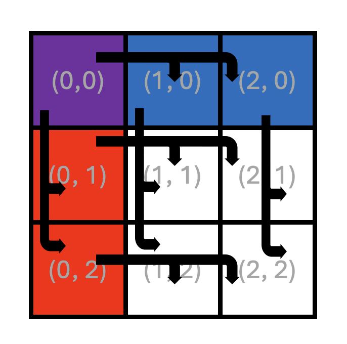
Figure 5: Core roles in Matrix Multiplication with Multicast
As a reminder, each square in Figure 5 represents a Tensix core labeled with its (x, y) core coordinates.
The thick arrows in the figure represent multicast operations.
While this figure shows a 3x3 core grid, the same pattern and analysis below apply to a grid of any size with four or more cores.
While computation remains the same on all cores, with each core computing its own output block C_block(x, y),
the multicast approach involves four distinct roles that cores play, indicated by different colors in the figure.
Recall that in Lab 2, data was divided into slabs to allow data to fit into limited on-chip SRAM.
With multicast, this approach stays the same. CB capacities, division of data into slabs and the slab
organization inside CBs remain the same. The main change that is required is for reader kernels to read
slabs of tiles of A and B differently depending on their role:
Interior cores (white background) with coordinates
(x, y), wherex > 0andy > 0: These cores never read slabs ofAorBdirectly from DRAM, but always receive them via multicast.-
Left column A-source cores (red background) with coordinates
(0, y), wherey > 0: Each of these cores:Reads slabs of
Ait needs for its own computation from DRAM and multicasts them across their rowy.Receives slabs of
Bfrom the topmost core in its column via multicast.
-
Top row B-source cores (blue background) with coordinates
(x, 0), wherex > 0: Each of these cores:Reads slabs of
Bit needs for its own computation from DRAM and multicasts them down their columnx.Receives slabs of
Afrom the leftmost core in its row via multicast.
Top-left core (purple background) with coordinates
(0, 0): This core reads slabs of bothAandBit needs for its own computation from DRAM. It also multicasts slabs ofAit read from DRAM to all the other cores in row0, and slabs ofBto all the other cores in column0.
What this translates to is that a matrix multiplication implementation with multicast will require four different types of reader kernels, corresponding to the four different roles identified above.
Similar to Exercises 2 and 3, we observe that the compute and writer kernels do not need to change at all. The compute kernel uses CBs for its data, without any awareness of whether the data was received via multicast or DRAM read. The writer kernel reads tiles from the output of the compute kernel, and also does not require any changes.
Exercise 4: Multi Core Matrix Multiplication with Multicast
In this exercise, you will start from your Exercise 2 solution from Lab 2 (multi core matrix multiplication with data reuse) and extend it to:
Use slab-level multicast for
Aslabs across rows,Use slab-level multicast for
Bslabs down columns,Retain the same blocked compute kernel and writer kernel,
Preserve correctness and then compare performance to the Lab 2 version. For this, you will use the same matrix sizes and core grid sizes as in Lab 2.
Perform the following steps to complete the exercise:
-
Set up a new project directory
Copy your Lab 2 Exercise 2 solution files into a new directory (e.g.,
lab3_ex4). Update theCMakeLists.txtfiles in the new directory and in the parent directory to include the new executable. Build and run the program to confirm that it still produces correct results before making any changes. -
Define core ranges for the four different roles
As described in Figure 5 and the accompanying text, the core grid is divided into four roles based on each core’s logical coordinates:
Define
CoreRangeobjects in your host code that contain logical coordinates for four core groups corresponding to the four different roles. These ranges should be used when callingCreateKernelto assign the correct reader kernel to each core group. -
Create semaphores for multicast synchronization
For A-slab multicast, create two semaphores on all cores: one “receivers ready” semaphore for receivers to signal readiness to the row’s A-source core, and one “slab sent” semaphore for the A-source core to signal that the slab has been multicast. Create an analogous pair of semaphores for B-slab multicast, for a total of four semaphores.
Although not every core will use every semaphore locally, creating all four semaphores on all cores ensures that
get_semaphorereturns the same on-chip SRAM address on every core for a given semaphore ID. This is required for the multicast protocol to work correctly, as described in the Semaphores: Local vs. Remote Access section earlier in this lab. -
Replace the single reader kernel with four role-specific reader kernels
In Lab 2, all cores used the same reader kernel that read both
AandBslabs from DRAM. Replace this with four separate reader kernels, one for each core role defined above. Each kernel implements a different combination of DRAM reads and multicast send/receive operations forAandBslabs. UseCreateKernelto create each kernel on the correspondingCoreRangedefined for the four core groups.The compute and writer kernels remain identical to Lab 2 and should continue to be created on all cores, just as before.
-
Implement the top-left core reader kernel
This kernel reads slabs of both
AandBmatrices from DRAM the same way as it did in Lab 2. However, it also needs to multicast slabs ofAandBto all other cores in the same row and column, respectively. To achieve this, it needs to take as kernel arguments the ranges of core coordinates to multicast to. Remember that these coordinates must be device coordinates, obtained viaworker_core_from_logical_core. It also needs to take as kernel arguments the IDs of the semaphores to use for the multicast operations. Then it needs to implement the sender side of the multicast protocol for bothAandBslabs, similar to the one described earlier in this lab.IMPORTANT: When forming the multicast destination address using
get_noc_multicast_addr, make sure to pass device coordinates in an order such that the “start” coordinates are always lower than the end coordinates. This is a requirement for theNOC0instance used by all reader kernels when using the default NoC mapping, as specified earlier in the lab. This applies to all the ranges of device coordinates that you will need to form in this exercise. While you technically do not know the values of the device coordinates, only logical coordinates, you can safely assume that relative ordering of values of device coordinates will correspond to the relative ordering of values of logical coordinates. For example, if the logical coordinates of the first and last receiver cores in a range are(0, 0)and(2, 2), the corresponding device coordinates will have some values(x0, y0)and(x1, y1). You can safely assume thatx0 < x1andy0 < y1. Thus,x0andy0should be passed as the start coordinates andx1andy1should be passed as the end coordinates. -
Implement the left-column core reader kernel
This kernel behaves differently with respect to slabs of the
AandBmatrices:Sends A slabs: reads slabs of
Afrom DRAM the same way as it did in Lab 2. However, it also needs to multicast slabs ofAto all other cores in the same row. This behavior is just a subset of the behavior of the top-left core described in the previous step.Receives B slab: Rather than reading
Bslabs from DRAM, this kernel receives theBslabs via multicast from the topmost core in its column. To achieve this, it needs to take as kernel arguments the device coordinates of the sender kernel (the topmost core in its column). It also needs to take as kernel arguments the IDs of the semaphores to use for the multicast operations. Then it needs to implement the receiver side of the multicast protocol for theBslabs, similar to the one described earlier in this lab.
-
Implement the top-row core reader kernel
This kernel mirrors the left-column kernel with
AandBroles swapped. All requirements are otherwise identical. -
Implement the interior core reader kernel
This is the simplest reader kernel. Rather than reading slabs of
AandBfrom DRAM, it receives both theAandBslabs via multicast from the corresponding source cores. If you already implemented the left-column and top-row kernels, you can reuse the code for these. Consider refactoring common code into helper functions to reduce the risk of copy-paste errors. -
Create appropriate reader kernels on appropriate core groups
Create the four reader kernels on the appropriate core groups using
CreateKernel. Use theCoreRangeobjects defined for the four core groups earlier in this exercise. DefineKernelHandleobjects for the four reader kernel groups to be used to set runtime arguments below. -
Set per-core runtime arguments
Update the host code to iterate over all logical core coordinates in the grid. For each core, determine its role based on its
(x, y)position and callSetRuntimeArgswith the appropriate arguments for that core’s reader kernel.In addition to runtime arguments used in Lab 2, sender kernels need:
Device coordinates of the first and last receiver cores in the multicast destination range (for use with
get_noc_multicast_addrin the kernel).Semaphore IDs for the relevant “receivers ready” and “slab sent” semaphores.
The number of receiver cores in the destination range.
Similarly, receiver kernels need:
Device coordinates of their source core (for use with
noc_semaphore_inc).Semaphore IDs for the relevant “receivers ready” and “slab sent” semaphores.
Be careful with coordinate systems:
SetRuntimeArgsis a host API that takes logical coordinates to identify which core receives the arguments, but any coordinates passed as runtime argument values must be device coordinates, obtained viaworker_core_from_logical_core. Perform all coordinate arithmetic (e.g., determining the core one position to the right or below, or the last core in a row) in logical coordinate space, then convert the final result to device coordinates. This is important because adjacent logical cores may not be adjacent in device coordinates due to non-compute cores in the physical layout (e.g., DRAM or Ethernet cores).Also keep in mind that
worker_core_from_logical_coreaccepts only valid logical coordinates. For example, it is not legal to pass in a logical coordinate outside the grid size or a negative coordinate, so make sure you structure all your computations to only result in legal logical coordinates. Finally,worker_core_from_logical_coreconverts only a single logical coordinate at a time, so if you need to convert a range of logical coordinates, you need to convert coordinates of the start and end of the range individually.It is a good practice to include “logical” or “device” in the names of all coordinate variables to avoid accidental misuse.
-
Build and verify correctness
Build and run your program and verify correctness in the same manner as in Lab 2.
If you encounter hangs, use the Watcher (as practiced in Exercise 1) and DPRINT statements to diagnose the issue. Common causes include incorrect semaphore updates, mismatched semaphore IDs between sender and receiver kernels, and incorrect device coordinates in multicast addresses. When debugging, consider reducing matrix and core grid sizes to simplify the problem while respecting divisibility constraints. Do not forget that you can debug host code using the usual debugger tools like
gdb. Remember to reset the device withtt-smi -rafter any hang.If the program runs but produces incorrect results, common causes include incorrect slab tile indexing, accidentally using
A-related addresses or semaphores forB(or vice versa), and incorrect runtime argument ordering. Use DPRINT statements to print runtime argument values and CB contents to identify the source of the mismatch. Remember that the output of DPRINT automatically indicates(x, y)logical coordinates of the core, but it does not automatically indicate the name of the kernel. Therefore, make sure to include a brief kernel name if the text of the DPRINT statement does not uniquely identify the kernel, while avoiding very long DPRINT messages, particularly in inner loops.If you are copy-pasting code segments between kernels, take extra care to update all variable names and parameters used in the copied code. Consider refactoring common code into helper functions to reduce the risk of copy-paste errors.
-
Profile performance
Once correctness is verified, profile both your Lab 2 implementation and your new multicast-enabled implementation using the device profiler. Ensure that you built the program with the Release option and that DPRINTs and Watcher are both disabled when profiling. Compare firmware times for the same matrix sizes and core grid configurations. Plot firmware time or speedup versus the number of cores and compare against:
Your single-core baseline from Lab 1,
Your multi core with data reuse implementation from Lab 2 (no multicast),
Your multicast-enabled implementation from this exercise.
You should observe that the multicast version reduces overall DRAM read traffic and can yield a measurable performance improvement.
Important Note If you observe that the multicast implementation performs worse than the data reuse implementation, it is likely because you are multicasting one tile at a time, rather than a slab at a time. In Lab 2, you had a choice of pushing one tile at a time or a slab at a time into the CB. If you pushed one tile at a time and simply added multicast to that solution, you would experience the handshake overhead we explored in Exercise 3. To achieve performance improvement, update your code to push a slab at a time into the CBs and also multicast the slab rather than individual tiles, similarly to how you modified your code in Exercise 3. When implementing this optimization, you should not issue a
noc_async_read_barrierafter each tile read from DRAM. Instead, you should issue a singlenoc_async_read_barrierafter all tiles in the slab have been read into the CB, similar to how it was done in Exercise 3 for batched tiles.
In this exercise, you have applied slab-level multicast to multi core matrix multiplication, combining the blocked compute structure from Lab 2 with the NoC multicast protocols practiced earlier in this lab. By reading each slab from DRAM only once per row or column and distributing it to all cores via multicast, you have reduced redundant DRAM traffic and demonstrated how cross-core data reuse can improve performance on Tenstorrent hardware.
Conclusion
In this lab, you refined the multi core matrix multiplication with reuse implementation from Lab 2 by adding
cross-core reuse of data via multicast, taking advantage of the regular pattern of data use across cores.
This was possible because all cores in the same row need the same data from the A matrix
and all cores in the same column need the same data from the B matrix.
Multicast is perfectly suited for this use case because it allows a sender core to write the same data
to multiple destination cores efficiently, in a single NoC operation.
This lab shows how higher-level algorithmic structure (blocked matrix multiplication with slabs) can be combined with low-level architectural features (NoC multicast and semaphores) to further reduce DRAM traffic and improve performance, without changing the core mathematical computation.
Additional information about the features used in this lab can be found in the following resources:
NoC (Network on Chip) Readme: https://github.com/tenstorrent/tt-isa-documentation/blob/main/BlackholeA0/NoC/README.md
Networks and Communication Lesson: https://github.com/tenstorrent/tt-vscode-toolkit/blob/main/content/lessons/cs-fundamentals-04-networks.md
Introduction to Data Movement in TT-Metal: https://github.com/tenstorrent/tt-low-level-documentation/blob/main/data_movement_doc/general/intro_to_dm.md
Watcher Documentation: https://firdovsimammedovk.github.io/tt-metal/tt-metalium/tools/watcher.html
Appendix A: Watcher Log File Format
The Watcher log file contains information about each Tensix core and its RISC-V processors. Each Tensix core has 5 RISC-V processors: BRISC, NCRISC, TRISC0, TRISC1, TRISC2, corresponding to RISC-V 0 through RISC-V 4 in the Tensix Core figure in Lab 1. BRISC is referred to as the primary processor, and the other RISC-V processors are referred to as subordinate processors.
The format is best explained by analyzing an example line:
Device 0 worker core(x= 1,y= 0) virtual(x= 2,y= 2): NSW,CWFW, K,MWDD, K rmsg:D0G|BNT h_id: 0 smsg:GGGG k_ids: 5| 6| 7| 7| 7
The meaning of the fields is as follows:
The first field identifies the device number (some systems may have multiple devices) and the logical and device (a.k.a. virtual) coordinates of the core.
-
This is followed by a comma-separated list of waypoints for BRISC, NCRISC, TRISC0, TRISC1, and TRISC2, respectively. Waypoints are usually single-character codes (e.g.,
W= Waiting,R= Running,D= Done), or multi-character codes (e.g.,NRW= “NoC Read Wait”,NSW= “NoC Semaphore Wait”). These codes correspond to the last waypoint encountered in that core’s execution. If you’re unsure what some of the codes mean, you can grep for the corresponding waypoint string in the source code. For example:grep -rn "." --include=\*.{cpp,h,hpp} -e 'WAYPOINT("CWFW")' ./tt_metal/hw/inc/api/dataflow/dataflow_api.h:476: WAYPOINT("CWFW");
You can then examine the code around line
476to better understand theCWFWwaypoint. The
rmsgfield shows basic info about the state of the Tensix core with respect to code being dispatched to this core. The first field indicates whether the kernels were dispatched to this Tensix core by the host (H) or by another core on the device (D). The second field indicates the NoC ID used by the primary processor (BRISC). Note that NCRISC uses the other NoC by convention. The third field indicates the state of the Tensix core with respect to code being dispatched to it: initialization (I), running/go (G) or done (D). This is followed by the|separator and then codes for different parts of the core being enabled/disabled. Uppercase letters mean a component is enabled (i.e., there is a kernel running on it), while lowercase letters mean it is disabled (i.e., there is no kernel running on it). For example,BNTmeans that BRISC, NCRISC, and TRISCs are all enabled, whereasBntmeans that only BRISC is enabled.The
h_idfield shows the internal program ID assigned by the host that is used for profiling.The
smsgfield shows the run state of the subordinate processors, using the sameI/G/Dcodes mentioned above.The
k_idsfield shows the ID of the kernel (by ID) loaded on each of the five processors on this core. The five values correspond to BRISC, NCRISC, TRISC0, TRISC1, and TRISC2, respectively.
Based on this, we can summarize the above line in the following table:
Field |
Value |
Meaning |
|
Logical coordinates |
This is logical core |
|
Device/Virtual coordinates |
Used for NoC addressing |
|
BRISC status |
NOC Semaphore Wait |
|
NCRISC status |
CB Wait For Write |
|
TRISC0 status |
In Kernel |
|
TRISC1 status |
Math Wait Data Dependency |
|
TRISC2 status |
In Kernel |
|
Run message |
Device dispatch, |
|
Host assigned ID |
Internal ID used for profiling |
|
Subordinate message |
NCRISC, TRISC0, TRISC1, TRISC2 in Go state (running) |
|
Kernel IDs |
BRISC=5, NCRISC=6, TRISC0/1/2=7 |
Kernels are identified by their IDs (k_ids). The mapping from kernel ID to source file name for a given section
is listed at the end of that section. For example:
k_id[  0]: blank
k_id[  1]: tt_metal/impl/dispatch/kernels/cq_prefetch.cpp
k_id[  2]: tt_metal/impl/dispatch/kernels/cq_dispatch.cpp
k_id[  3]: tt_metal/impl/dispatch/kernels/cq_dispatch_subordinate.cpp
k_id[  4]: ttnn/examples/lab_multicast/kernels/dataflow/mcast_sender.cpp
k_id[  5]: ttnn/examples/lab_multicast/kernels/dataflow/mcast_receiver.cpp
k_id[  6]: ttnn/examples/lab_multicast/kernels/dataflow/write_tiles.cpp
k_id[  7]: ttnn/examples/lab_multicast/kernels/compute/tiles_copy.cpp
Idle cores, where the program has not created any kernels, can easily be identified by their k_ids fields all set to 0.
Together with waypoints, asserts, and DPRINTs, this log format turns Watcher into a practical tool for quickly pinpointing the cores, kernels, and code locations involved in hangs and other hard to debug issues.